Introduction
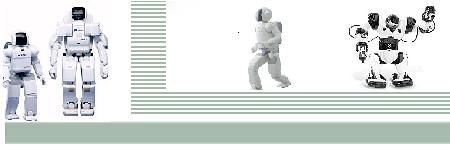
The arm control by robotics is very popular in the world of robotics. The essential part of the robotic arm is a programmable micro controller based brick capable of driving basically three stepper motors design to form an anthropomorphic structure. The first design was for experimental use on a human size industrial robot arm called PUMA 560 .This article explains the method of interfacing the robotic arm stepper motors with the programmed 8051-based micro controller Keywords: MCU, PUMA, PIO, LATCH, I/O Objective: Our primary objective is to make the Robotic arm, having three stepper motors, to interface with the In-Development of a Microcontroller Based Robotic Arm tel 8051-based micro-controller. It provides more interfaces to the outside world and has larger Memory to store many programs Approach: We were able to perform a detailed study of the robotic arm and the 8051 micro-controller. We Tested the built robotic arm, and the stepper motors when the robot is loaded. We also learnt and Familiarized with the 8051 micro-controller using assembly language, and converting the assembly language codes to hexadecimal codes using a development board. Mechanical Structure of the Arm: In constructing our arm, we made use of three stepper motors and gears since our structure is a three dimensional structure. A typical prototype that we employed is as shown in Figure.There is a stepper motor at the base, which allows for circular movement of the whole Structure; another at the shoulder which allows for upward and downward movement of the Arm; while the last stepper motor at the wrist allows for the picking of objects by the magnetic hand.
Micro-Controller:  The various components of the MCU shown in Figure 2 are explained below: The various components of the MCU shown in Figure 2 are explained below:
Random Access Memory (RAM): RAM is used for temporary storage of data during runtime. ROM: ROM is the memory which stores the program to be executed. SFR Registers: Special Function Registers are special elements of RAM. Program Counter: This is the "engine" which starts the program and points to the memory address of the instruction to be executed. Immediately upon its execution, value of counter increments by 1. Control Logic: As the name implies, it which supervises and controls every aspect of operations Within MCU, and it cannot be manipulated. It comprises several parts, the most Important ones including: instructions decoder, Arithmetical Logic Unit (ALU) and Accumulator. A/D Converter: A/D stands for analog to digital. They convert analog signals to digital signals. I/O Ports: To be of any practical use, microcontrollers have ports which are connected to the pins on its case. Every pin can be designated as either input or output to suit user’s needs. Oscillator: This is the rhythm section of the MCU. The stable pace provided by this instrument allows harmonious and synchronous functioning of all other parts of MCU. Timers: timers can be used for measuring time between two occurrences and can also behave like a counter. The Watchdog Timer resets the MCU every time it overflows, and the program execution starts anew (much as if the power had just been turned on). Power Supply Circuit: this powers the MCU. Methodology The method employed in designing and constructing the robotic arm are based on the operational Characteristics and features of the microcontrollers, stepper motors, the electronic circuit diagrams and most importantly the programming of the microcontroller and stepper motors. Block Diagram  The block diagram of our work is as shown in Figure The block diagram of our work is as shown in Figure
Circuit Diagram  The electronic circuit diagram of the development board is as shown in Figure 4. The connection of the identified components and devices are as shown. The components shown are: the MCU, the LATCH 74LS373, the EPROM 2732, Intel 8255 PIO, diodes, resistors, capacitors, inductors, transistors, and op-amps. This components work together to achieve the set goal of controlling the anthropomorphic-like arrangement of the stepper motor. The microcontroller is the processing device that coordinates all the activities of all the components for proper functioning. The electronic circuit diagram of the development board is as shown in Figure 4. The connection of the identified components and devices are as shown. The components shown are: the MCU, the LATCH 74LS373, the EPROM 2732, Intel 8255 PIO, diodes, resistors, capacitors, inductors, transistors, and op-amps. This components work together to achieve the set goal of controlling the anthropomorphic-like arrangement of the stepper motor. The microcontroller is the processing device that coordinates all the activities of all the components for proper functioning.
Power Supply This is used to power the whole system i.e. the Control Unit, Magnetic Sensing Unit, and the Stepper Motors. The transformer is a 220/12V step down transformer. We used a bridge rectifier to convert the 12V alternating current to direct current. The unregulated output from the filtering circuit is fed into a voltage regulator LM7805 andLM7812. These two are chosen for the design because the LM7805 has an output of +5V which’s required to power the Control Unit, and the Magnetic Coil while the LM7812 has an output of +12v which is required to power the Stepper motors. The TIP41 connected to the IC regulators functions as an emitter follower amplifier making sure that at least the required voltage by the Control Unit, the Magnetic Coil and the Stepper Motors produced. MCU 8051 This is the processor. It coordinates the operation of the robotic arm by collecting information from the EPROM, the LATCH, and the PIO; interprets and then execute the instructions. It is the heart of the whole system. LATCH 74LS373 This is a D-type transparent latch. It is an 8 bit register that has 3 state bus driving outputs, full Parallel access for loading, and buffer control inputs. It is transparent because when the enable
EN(enable) input is high, the output will look exactly like the D input. This latch particularly Separates the data and address information from the MCU before sending to the instructed destination.The high-impedance state and increased high logic-level drive provide these registers with the capability of being connected directly to and driving the bus lines in a bus-organized system without need for interface or pull-up components. These latches are particularly attractive for implementing buffer registers, I/O ports, bidirectional bus drivers, and working registers.We are using this latch because there is a need to separate our 8 bit data and 8 bit address information from the common line of the MCU, and send them to the appropriate device(s). 8255 PIO This is a programmable input/output device. It interfaces the connection between the 8051, the LATCH 74LS373, and the EPROM 2732 to external devices such as the stepper motors, (as is our own case) thereby allowing for communication. (EPROM) 2732 EPROM stands for Electrically Programmable Read Only Memory. We made use of this external EPROM specifically because it makes the controller cheaper, allows for longer programs, and Because its content can be changed during run time and can also be saved after the power is off The overall diagrammatical layout of the complete circuit diagram of the whole control unit is shown in Figure. Stepper Motor The stepping motor is a motor that is driven and controlled by an electrical pulse train generated by the MCU . Each pulse drives the stepping motor by a fraction of one Revolution, called the step angle. The Magnetic Sensing Unit The magnetic sensing unit consists of a magnetic coil which can be magnetized simply by the action of the port P1.0 of the 8051. The port 1.0 was made use of because when designated as output, each of the pin can be connected up to four TTL inputs. That is why we have connected the pin 1.0 to the magnetic coil through three TTL logic The design is such that on the downward movement of the wrist, the 8051 sends an electrical signal to the Darlington pair connected to the magnetic coil. The magnetic sensing unit is powered on by three BC548 Darlington NPN pair transistor, through a diode each and a 5k resistor. The pair amplifies the current and makes the magnetic coil turn into magnet. Then any magnetic material could be picked (by attraction) and then movement continues. The magnetic material can then be dropped at another point when the wrist is made to come down, this also is an action from the 8051 as it withdraws the electrical signal from the coil. Control Circuit This is the control panel of the system as it oversees the operations of the mechanical arm, and the magnetic sensing unit. The MCU 8051 of the control unit acts as the brain of the control panel as it coordinates all the activities of the other devices. When power (+5V) was supplied to the control unit, the MCU started off by loading the program from the EPROM M2732A, interpreted and executed the instruction codes through the various operational principles which had been described in details in chapter three (session 3.2).The 8051 then sends signal to the stepper motor which moves 9° per step. The stepper motor(M3) at the wrist first moves five times (45°) turning the gears to cause a downward movement of the hand. The stepper motor at the shoulder (M2) moves next stepping five times (45°) and makes the connected gears to cause the movement of the arm 45° forward. Then the stepper motor at the base(M1) moves either ten times (90°) or twenty times (180°), depending on the button pressed, causing the whole structure to turn from right to left( or vice versa) through the connected gears. The magnetic coil resting on the hand becomes magnetized immediately the last gear on the hand stops moving. Then, it magnetizes (picks) any magnetic material it can find and then M3 and M2 moves the arm up while M1 moves (rotates the structure) from left to right (or vice versa) and then the 8051 demagnetizes the magnetic coil thereby making the hand to drop the metallic object. Results This work is able to successfully accomplish the defined functionality. A sample robot which can rotate, magnetize an object, lower and raise its arm, by being controlled by the 8051 microcontroller is built successfully. The 8051-development board is soldered and it used the required procedure for the correct operation of the controller. The 8051 development board has been interfaced to the stepper motors such that the anthropomorphic like structure can be controlled from the buttons at the base of the structure (robotic arm). There are four buttons being controlled by the control unit at the base of the arm: • ON/OFF: the ON button puts on the system while the OFF button puts off the system • START/STOP: the START button starts the movement of the whole arm from its reset point, while the STOP button takes the arm back to its reset button after completion of its movement. • RIGHT-LEFT/LEFT-RIGHT: when this button is switched to the RIGHT-LEFT part it causes movement from right to left, while the LEFT-RIGHT part causes movement from left to right. • 180/90: when the button is on 180, it causes a rotation of 180 degree of the base stepper motor, but when put on 90 degrees, it causes rotation of 90 degrees. Labels: MicroController, Robotic Arm |


This information about how to make robotic arms interesting, I hadn't realized stepper motors were used to make them before.